I modified or created, as applicable, the following software to use with my RS-HFIQ and a Raspberry Pi 4.
quisk-4.1.52
This is a version of Quisk 4.1.52 that I modified to implement a GPIO Keyer. Note that the git repo linked above includes all of the source code… it should be a ready-to-go source bundle for you to download, make and install! The setup script should only include/compile the Keyer code if it detects the WiringPi library (via the presence of wiringPi.h). This code has only been tested on a Raspberry Pi 4, but I suppose it might work on any device that supports WiringPi.
Hardware requirements:
- Raspberry Pi 4 (others untested)
- GPIO interface to your paddles (see below)
- RS-HFIQ (or other SDR, but this is what I’ve tested)
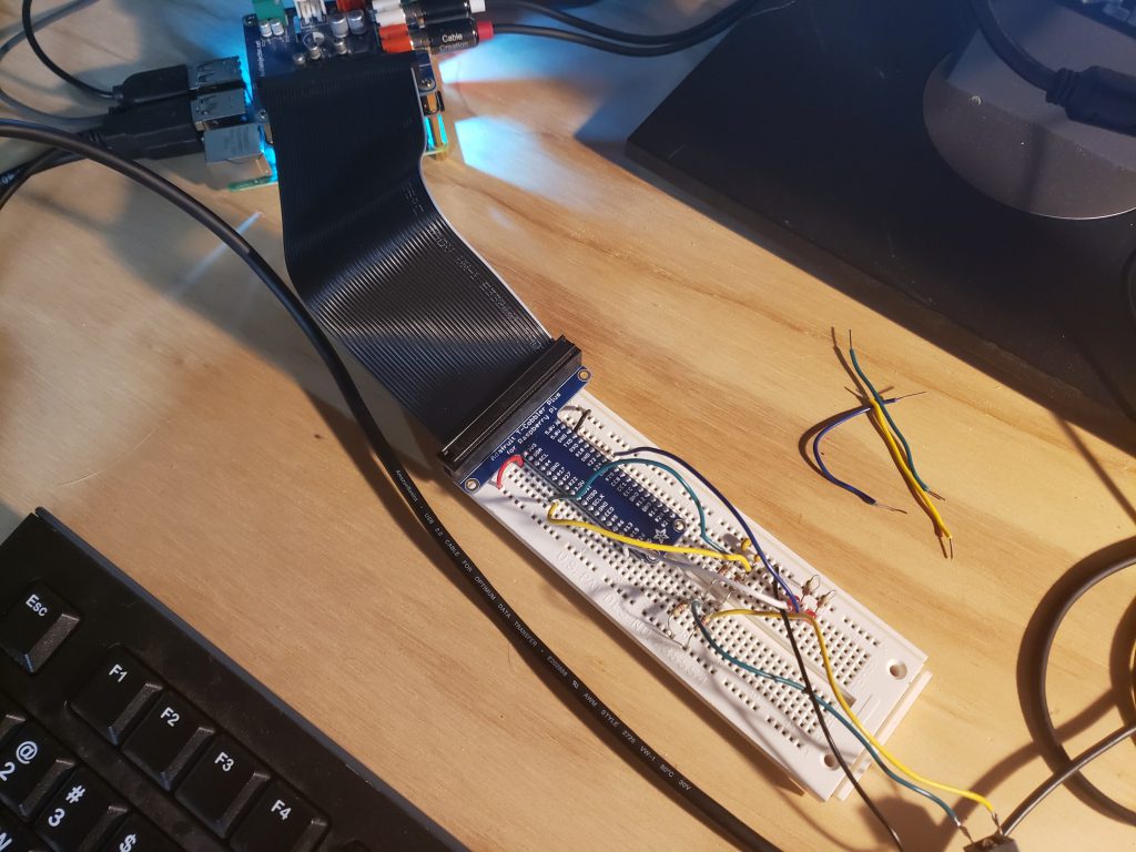
I’ll have to add a detailed hardware setup at some point. Big picture, you need two available GPIO pins for paddle input, and optionally, two GPIO pins for CW and T/R switch output (although I currently just use Quisk to internally generate the CW, and USB serial for T/R control of my RS-HFIQ). In my setup, I use GPIO 27 + GPIO 2 for the paddles, and GPIO 24 + GPIO 26 for the outputs (which currently just drive a couple of LEDs). Here’s a quick picture.
Software requirements:
You’ll need the modified Quisk software downloaded from my site. You can run the following command in the terminal on your Pi to retrieve it with git. This will extract it into a folder called quisk-4.1.52.
git clone http://scrape.sdf.org/kc4upr/quisk-4.1.52.git/
Then, make/install Quisk per the following instructions:
cd quisk-4.1.52
git checkout gpiokeyer  # to switch from master branch to gpiokeyer branch
make quisk2
make install
Add something like the following to your $HOME/.quisk_conf.py file. Note that you will probably still have to do some Python work to make this all work for you. If you have an RS-HFIQ, you can jump down to the pi-hfiq section below.
key_method = "gpio:22,27,26,24"
In this case, pin 22 is the left paddle, 27 is the right paddle, 26 is the CW output (optional), and 24 is the T/R switch. Note that these all use “GPIO-style” pin numbers rather than “WiringPi-style” pin numbers.
The Keyer code was adapted from the Raspberry Pi iambic keyer code created by N1GP.
quisk-gpiokeyer
If you don’t want to download all of the Quisk source code from here (maybe you have already made your own mods to the source), then you can alternatively download a ‘diff’ file suitable for use with ‘patch’. You can use that to update your own copy of the Quisk source. You can download the file here: quisk-4.1.52-gpiokeyer-0.1.diff_.gz
Copy the file to the folder where you have your Quisk source code (e.g. quisk-4.1.52), open up a terminal in that folder, and then do the following:
gunzip quisk-4.1.52-gpiokeyer-0.1.diff_.gz
patch -p1 <quisk-4.1.52-gpiokeyer-0.1.diff_
Your Quisk source code should now be modified with the keyer code, and you can build it as described in the previous section.
pi-hfiq
The GPIO Keyer for Quisk does not require an RS-HFIQ. However, if you have an RS-HFIQ, you can use my Pi-HFIQ hardware definition for Quisk to enable/run the Keyer, as well as perform setup and control of the rig via the USB serial interface (with some modification, I’m sure you could use this for other SDR rigs as well, or maybe just grab the pieces that I use to setup the Keyer). Run the following in a terminal to get the goods:
git clone http://scrape.sdf.org/kc4upr/pi-hfiq.git/
You should now have a folder with two files, hardware_pihfiq.py and widgets_pihfiq.py. Configure those in Quisk just as you normally would. You’ll also want to update your $HOME/.quisk_conf.py with the following (make sure to replace the pin numbers in the first line with the GPIO pins that you are using).
key_method = "gpio:22,27,26,24"
key_poll_msec = 5
key_hang_time = 0.25
use_sidetone = 1
The pin order is: left paddle, right paddle, CW output, T/R switch output. If you don’t want to use the last two, you can just set them to zero (not tested… but should work…).
Cross your fingers and launch Quisk…