Introduction
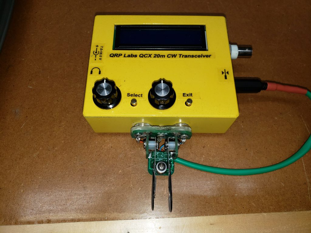
I identified a need to have an RF wattmeter somewhat more accurate than the forward/reflected power meter built-in to my N7DDC antenna tuner. I decided to with a “digital dummy load” approach, similar to what I had seen in Arduino Projects for Ham Radio. However, as I was not able to checkout the copy my local library has at the moment, I found this Digital Dummy Load design by KC9ON. It seemed pretty straightforward, and had enough info with it to help me adapt it for my QRP uses. However, I did not want to have to order all of the necessary resistors and build up the whole resistor assembly… so I decided to use my QRP Labs 50-ohm 20W QRP HF Dummy Load for the dummy load section of the project. Here’s a quick picture of the whole thing together:
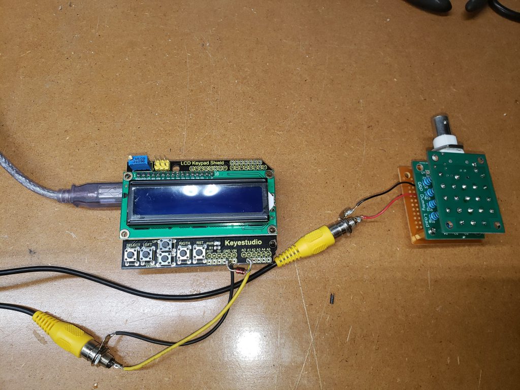
On the left is the Arduino UNO with a shield containing both a 16×2 LCD display and 6 pushbuttons (Select, Left, Right, Up, Down, Reset). On the right is the QRP Labs 50-ohm 20W QRP HF Dummy Load with the adapter board from the KC9ON design on it. I actually used this Keyestudio UNO R3 clone and a display by the same manufacturer, both of which I purchased from Jameco. One issue I noticed with this particular combination is that, if I fully seated the display shield all the way down onto the UNO headers, the bottom of some of the header pins would ground out against the USB port housing. I solved this for now by (a) putting some electrical tape over the top of the USB port, to insulate it, and (b) not seating the display shield all the way down. In the future though, this will require either some very specific length standoffs, or slipping in some kind of shim to maintain the appropriate separation between the two boards.
Design Changes
I specifically intended for my version of the Digital Dummy Load to (a) use my QRP Labs 50-ohm 20W QRP HF Dummy Load, and (b) be for QRP operations (up to the 20W max of the dummy load).
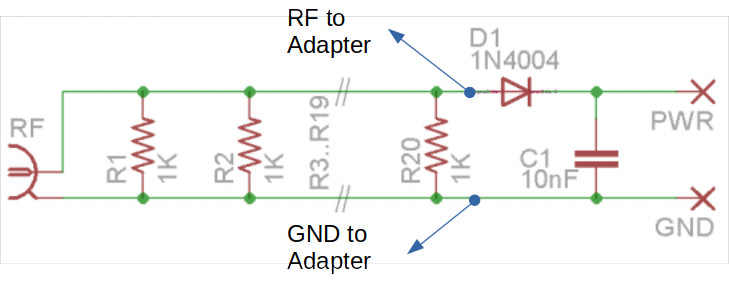
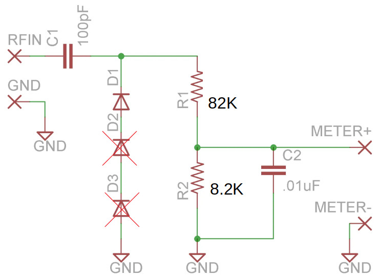
I didn’t make any real changes to the QRP Labs dummy load itself, other than soldering some wires to it. I decided I wanted to use the RF probe method of measuring the peak RF voltage, rather than the rectifier method that is already included in the dummy load (combination of a 1N4004 rectifier diode and a filter capacitor). I don’t actually know that the RF probe method is more likely, but that was my initial reaction. I didn’t remove the existing diode and capacitor, I just figured I’d leave them as is and add a separate connection, as depicted in the modified QRP Labs schematic below. My assumption is that leaving the existing output circuit, albeit disconnected, will have negligible effect on my added measurement circuit… hopefully that assumption is valid! Again, I leave the existing PWR and GND connections disconnected, and route new wires to the adapter board.
Next up, the adaptor board, which converts the RF to the DC voltage to be read by the Arduino analog-to-digital converter (ADC)… The changes I made were based on using this with a 20 watt dummy load–I made the assumption that it will never have to measure more than 30 watts (e.g. if I put the dummy load in oil, as well as to give the ADC a little margin).
First, I eliminated D2 and D3. The original design used a series of three 1N4148 diodes to handle the peak voltage associated with up to 250 watts (about 55 V into a 50 ohm dummy load).
Then, I adjusted the resistor voltage divider with a larger ratio, for better sensitivity at lower power levels (up to 30 watts). The 82K and 8.2K resistors give an 11:1 ratio, so with 55 V in (from a 30 W transmitter), I would get 5 V out to the Arduino’s ADC.
Here’s the modified (scribbled on) schematic.
Assembly
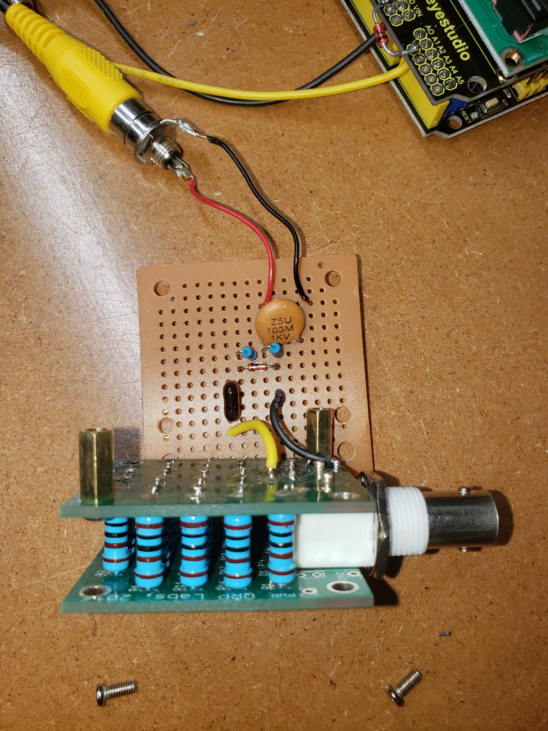
Assembly was essentially in accordance with the instructions on KC9ON’s page. Here’s a picture of the dummy load, with the adapter board wired to it. Sorry, I forgot to take a picture before I soldered them together. The adapter board is just wired up on an old piece of Radio Shack protoboard. The yellow wire is the RF output from the dummy load, and the black is ground. For the DC output, I’ve wired up an RCA jack
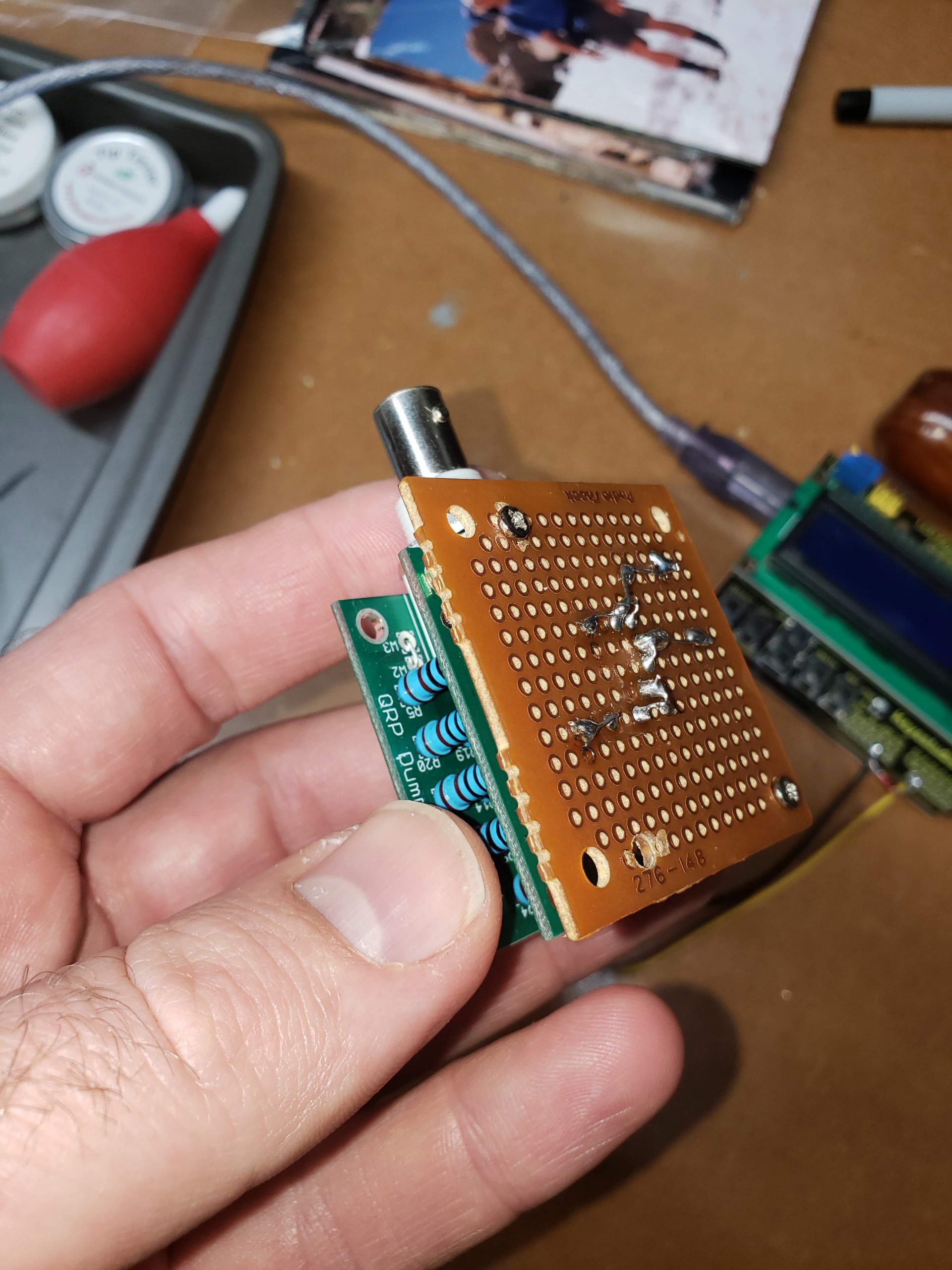
I used a pair of brass standoffs to connect the adapter to the back of dummy load. The protoboard is a little bigger than the dummy load PCB’s, so I had to drill a couple of extra holes. The idea is that these fit together, and then could be mounted in the same box, can of mineral oil, etc., and the processor/display would be remotely located, connected via a shielded cable. Here’s a picture of the completed assembly. I haven’t decided what I’ll put it in yet.
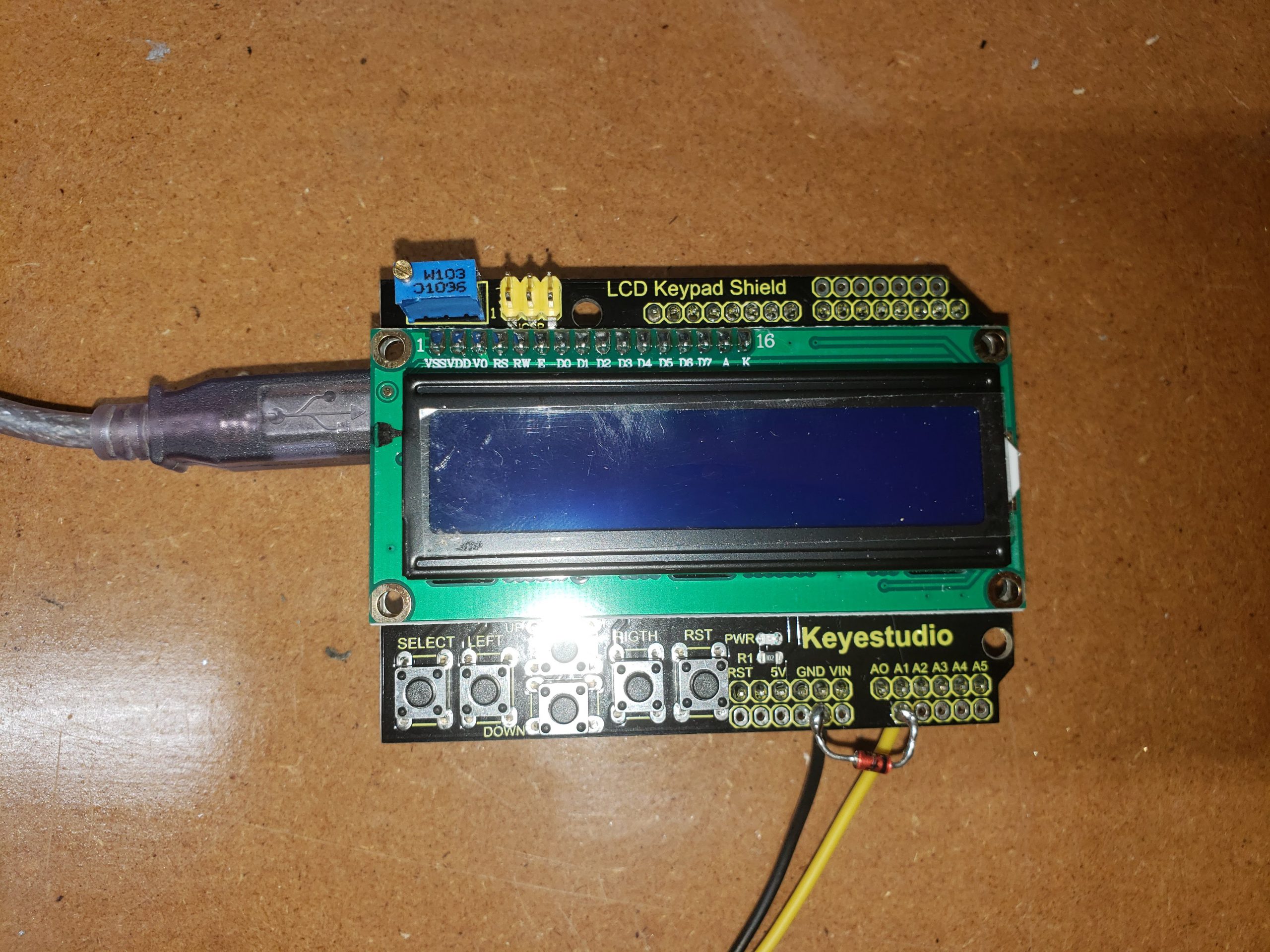
Here’s the Arduino UNO R3 with the attached 16×2 LCD/switch shield. The original schematic calls for a 1N5231 5V Zener diode between pin A1 and ground, to protect the Arduino from over-voltage on the input pin. I had a slightly different Zener diode available, a 1N4733A, rated to 1 W (rather than 500 mW), so I went with that. After soldering in the wires for the RCA jack, I soldered the diode across the two pins (A1 and ground) on the display shield.
To be continued…
Part 2 should go through Software, Calibration, and Performance.